BRAAD
Ball Receiving Autonomously Actuated Device
Overview
Robots are often used for tasks that require identifying and safely manipulating objects in an environment. Many robotic manipulators have demonstrated catching objects, which involves tracking the trajectory of a moving target and intercepting it. By grasping the object mid-air with an end-effector, these manipulators successfully demonstrate the impressive speed of their control system. However, the grasping action occurs in an instant, causing sudden, harsh forces on the object and gripper as the object decelerates instantaneously. Thus, without any way to compensate for these forces (such as mechanical compliance in the manipulator joints), this method of interception could damage the object being grasped, especially if it is fragile (such as an egg). In other cases, the manipulator itself could be damaged from the sudden external load, for example, if it was intercepting a heavy package.
BRAAD (Ball Receiving Autonomously Actuated Device) is a robotic manipulator designed to track and gently decelerate a moving target using visual feedback. This will be demonstrated through the task of soccer ball trapping, a maneuver that involves “capturing” a moving soccer ball as it approaches by gently applying a controlled force to decelerate the ball until its velocity reaches zero. In human soccer games, players typically perform trapping by contacting the ball with an outstretched foot and continuously tracking the ball with their foot, keeping it in contact as the ball moves to apply the deceleration force.
BRAAD is designed to actively manipulate the trajectory of a moving soccer ball based on its real-time position and velocity. As the ball approaches, the system will use visual feedback to track the ball’s position and velocity as it approaches in order to determine where the end-effector should be placed to successfully intercept the ball. Before the ball makes contact, the robot will move its end-effector along the ball’s predicted path in order to prevent it from bouncing off. Once contact is established, BRAAD will gently slow down the ball similar to the human case.
This method of predictive trapping can potentially be extended for use in a variety of robotic manipulators, especially ones that require intercepting moving objects. This will increase the safety of the system for both the object being handled, as well as the robot itself. A demonstration of the system in action is shown in the video below.
Objective
The objective of the BRAAD robotic system is to actively manipulate the trajectory of a moving target based on that target’s real-time position and velocity. The task to represent this objective is modeled as a manipulator robot that traps a rolling ball. The act of trapping occurs most frequently in the sport of soccer, where an athlete cushions an incoming pass and reduces the ball’s momentum such that it comes to rest underneath or out in front of the athlete. As the receiving foot moves with the same velocity as the ball, the collision time is extended. The trapping motion of a professional athlete also often directs the ball downward, where momentum can be dissipated into the ground or through deformation of the ball.
Trapping a ball is different from simply catching a ball, as the act of trapping does not utilize grasping abilities normally associated with manipulator arms. This technique relies purely on the dynamic contact and motion of its end-effector. The ball’s real-time position and velocity can be obtained using vision to plan the trajectory of the end-effector (foot) at impact.
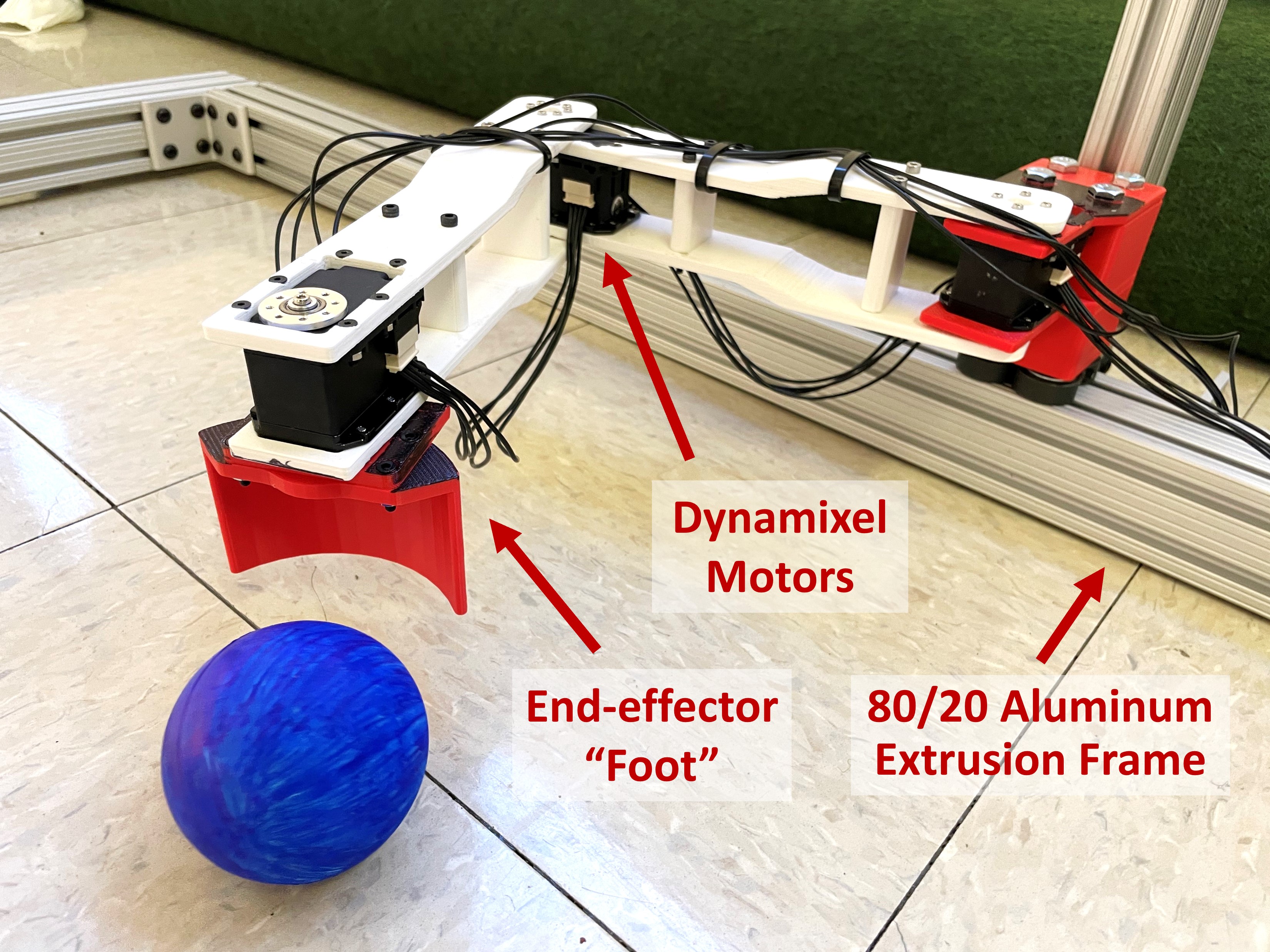
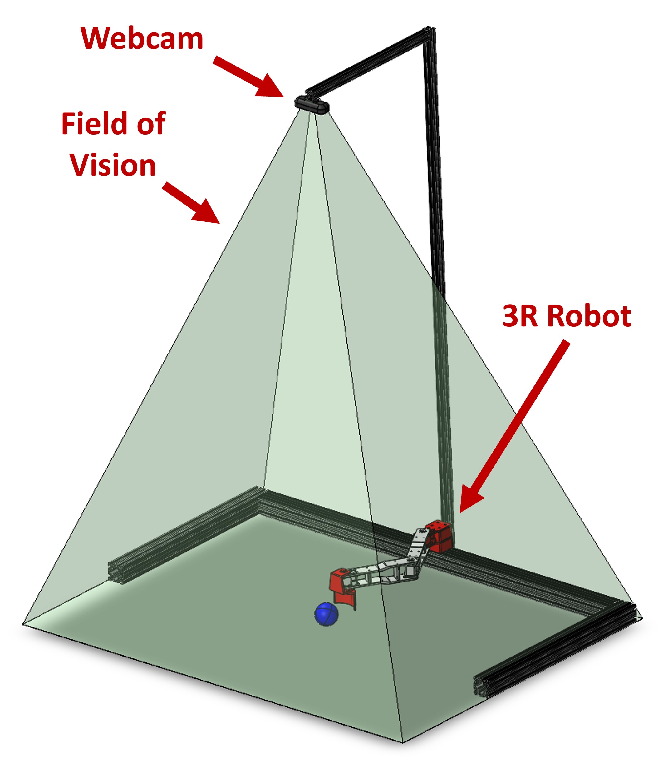
To this end, BRAAD consists of a combined robotic arm and visual sensor system. The robotic platform is designed to serve as the “leg” with an end-effector “foot” that interacts with balls in the environment, and is comprised of rigid links with dynamixel motors as the joints, as seen in Figure 1. The visual sensor is a camera mounted above the task space, pointing directly downwards to view the ball and robotic arm in the floor plane, as depicted in Figure 2.
The system’s main objective is to successfully perform a trapping sequence on a rolling ball moving at an arbitrary angle and initial velocity when the ball enters the task space. This involves the end-effector moving to the predicted path of the ball, matching the ball’s velocity, establishing contact, and then bringing the ball to a stop.
To successfully perform a trapping maneuver, BRAAD must perform the following sequence of tasks:
- Sense the position and velocity of the ball as it approaches the workspace
- Predict the ball’s trajectory as it travels through the workspace
- Identify an optimal point of interception with the ball.
- Generate joint trajectories
The calculated joint trajectories will then perform the following tasks:
- Move the end-effector to the interception point
- Travel along the predicted ball trajectory, and establish contact with the ball at its current velocity (to avoid the ball bouncing off).
- Slow down the ball by gradually reducing the end-effector velocity until both the robot and ball are at rest.
Physical Hardware Design
BRAAD’s robotic arm is a 3R planar robot comprised of two links and one end-effector. All parts are 3D printed out of ABS. The arm is mounted on a frame made of 80/20 T-slot extrusion that serves as the ground for the arm and outlines the workspace. The arm link lengths were chosen to be 19 cm each, based on the scaling factor compared to the length of an average human leg. Each of the three joints is actuated by a Dynamixel MX-28AR (193:1 gear ratio). The end-effector has a curved surface that decreases the likelihood of the ball bouncing away from the end-effector in the event of a small angle misalignments. This is because the angled surface will cause the ball to bounce towards the center of the curve, which assists in capturing the ball.
All components are wired to interface with a laptop computer. The computer uses MATLAB to coordinate between the vision system, trajectory generation subroutines, and motor controllers.
Vision System Design
The purpose of this sub-system is to identify the incoming ball, determine its position in operational space, and then continually estimate an incoming ball trajectory that feeds into our controller. A DEPSTECH 4K webcam is mounted 1.5 m above the floor plane on an additional 80/20 frame, giving the camera a view the entire operational space. A bubble leveler was used to ensure the image data would have minimal perspective shifts, allowing one pixel to translate directly to one X-Y coordinate on the floor plane. Distortion is expected to occur on the outer edge of the cameras image, but is assumed to be negligible given the minimal distance between the camera and the workspace. Despite the DEPSTECH’s 4K capabilities, an output resolution of 720x1280 pixels was used because high resolution is not a priority and the chosen resolution still clearly displays both the manipulator arm and the blue ball within its field of view. MATLAB’s Computer Vision and Image Processing toolboxes was used to conduct a frame by frame analysis to determine the ball’s position. The computer vision system does region-based image segmentation based on area and interprets the centroid of the region as the center of the ball with respect to time. Using the 5 most recently recorded position coordinates of the ball and the corresponding time values, a prediction of the ball’s trajectory was made based on a first order polynomial. The predicted trajectory (Figure 3) and the current position of the end-effector was used to determine the point of interception of the ball.
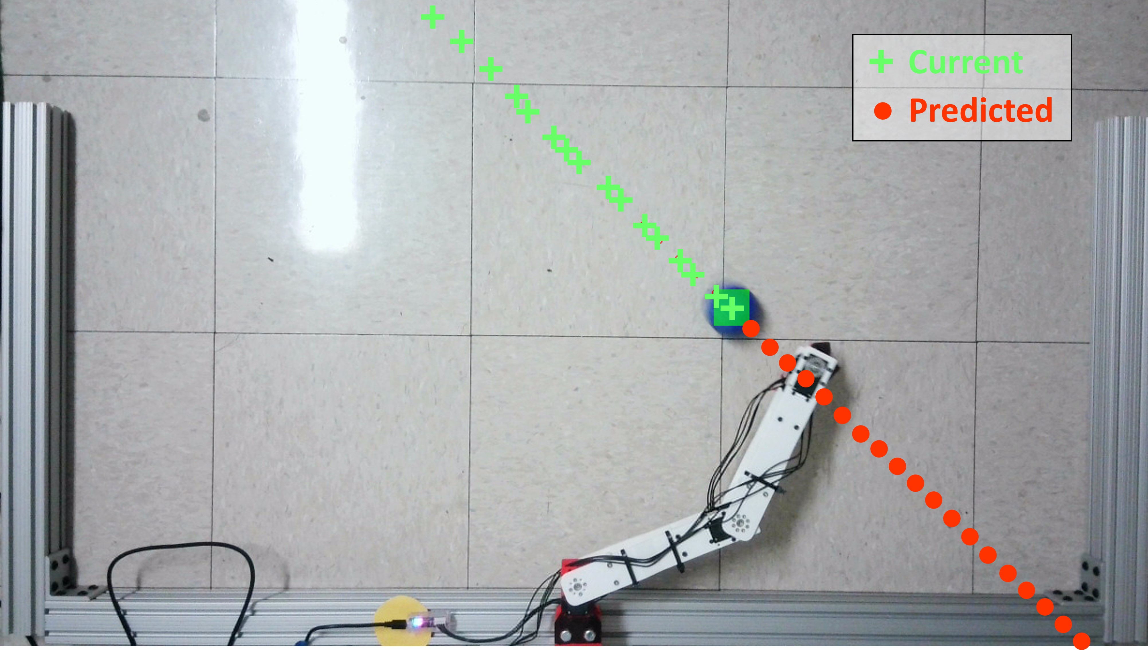
Below are two videos of the ball trajectory prediction algorithm working live. The green dots are a history of the ball’s positions and the red dots are predicted future positions of the ball.
Controller Requirements
To successfully complete the task of trapping, BRAAD’s controller must be able to meet the following design requirements:
- Allows for joint speeds sufficient to intercept a ball from an arbitrary position, orientation, and velocity that approaches from outside of the workspace.
- Reaches the interception position and settles within 0.5 seconds. This is to ensure the end-effector is not still moving by the time the ball reaches the manipulable space. The settling time was chosen based on the worst case scenario where the ball is approaching head-on with maximum velocity from the minimum distance detectable by the camera (2 ft or 609 mm).
- Accurately matches the end-effector’s velocity to the ball’s velocity at the time of contact to prevent the ball from bouncing off.
- Computationally efficient enough to run simultaneously with the vision system.
To meet these requirements, we decided to utilize two controllers in sequence:
- Stage 1: Joint space decentralized feedforward position control, activated when moving the arm to the interception point.
- Stage 2: Global space decentralized feedforward velocity control, activated to contact the ball at its velocity and decelerate to a rest.
Decentralized control is viable given the high gear reduction ratios of the Dynamixel motors (193:1), but also relies on other assumptions:
- The ball has low initial velocity. This is to meet the “relatively small joint actuation torques” requirement for using decentralized control. We determined a maximum initial velocity of 1 m/s to be sufficient given the downscaled nature of the system.
- The motors are relatively efficient and links are relatively low mass, so nonlinear behaviors due to coupling can be ignored.
- The ball has negligible mass. This is to simplify the control problem by treating it as motion in free space, ignoring external forces or torques that might be generated from the ball impacting the end-effector during contact.
- The surface is flat. The trajectory of the ball can be modeled as straight line motion. Decentralized control simplifies the controller significantly due to the linearized system dynamics, which decreases the computational load and increases speed. By skipping the computation required for dynamic controllers, computation time can be drastically reduced. Additionally, during the first stage, where the end-effector’s trajectory in global frame is not important, joint space control can be used. This simplifies the process of sending commands to the Dynamixel motors, but requires necessary conversions for the ball which will be moving in X-Y in the global frame. Feedforward compensation can be utilized since desired trajectories need to be generated ahead of time with the vision system in order to calculate where to move the arm. These trajectories can be fed forward into the controller to help reduce tracking errors that might result from high speeds or accelerations during the relatively quick intercepting motion.
Controller Design
To trap an incoming ball, the system must perform many preliminary and real-time calculations in order to analyze the ball and generate trajectories to feed into the position or velocity controllers. Since we wanted to reduce computing time whenever possible, certain steps were pre-calculated based on BRAAD’s physical parameters to assist the controller in generating desired trajectories.
Point of Interception
If the ball’s predicted trajectory were to cross the robot’s workspace, there are numerous locations where the end-effector could intercept the ball. Below is a 2D simulation of where BRAAD could theoretically track the ball’s trajectory.
In addition to intercepting the ball, because BRAAD needs to interact with the ball, manipulability, a measure of how much velocity or force the end-effector could produce, was used as a metric to decide the point of interception. The forward kinematics of the planar 3R system was derived to compute the manipulability. For link lengths \(L_{1}\), \(L_{2}\), and \(L_{3}\), with joint angles \(\theta_{1}\), \(\theta_{2}\), and \(\theta_{3}\), the forward kinematics for the system are:

These equations were used to find the Jacobian \(J\) by calculating:
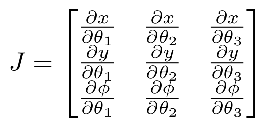
Performing this calculation yields:

The Jacobian was then used to compute the manipulability \(w\) for a given point in the workspace.

The manipulability of the robot across the entire workspace was analyzed using the Monte Carlo method (Figure 4), where the red points indicate regions of higher manipulability. A circular region of highest manipulability can be observed from the analysis.
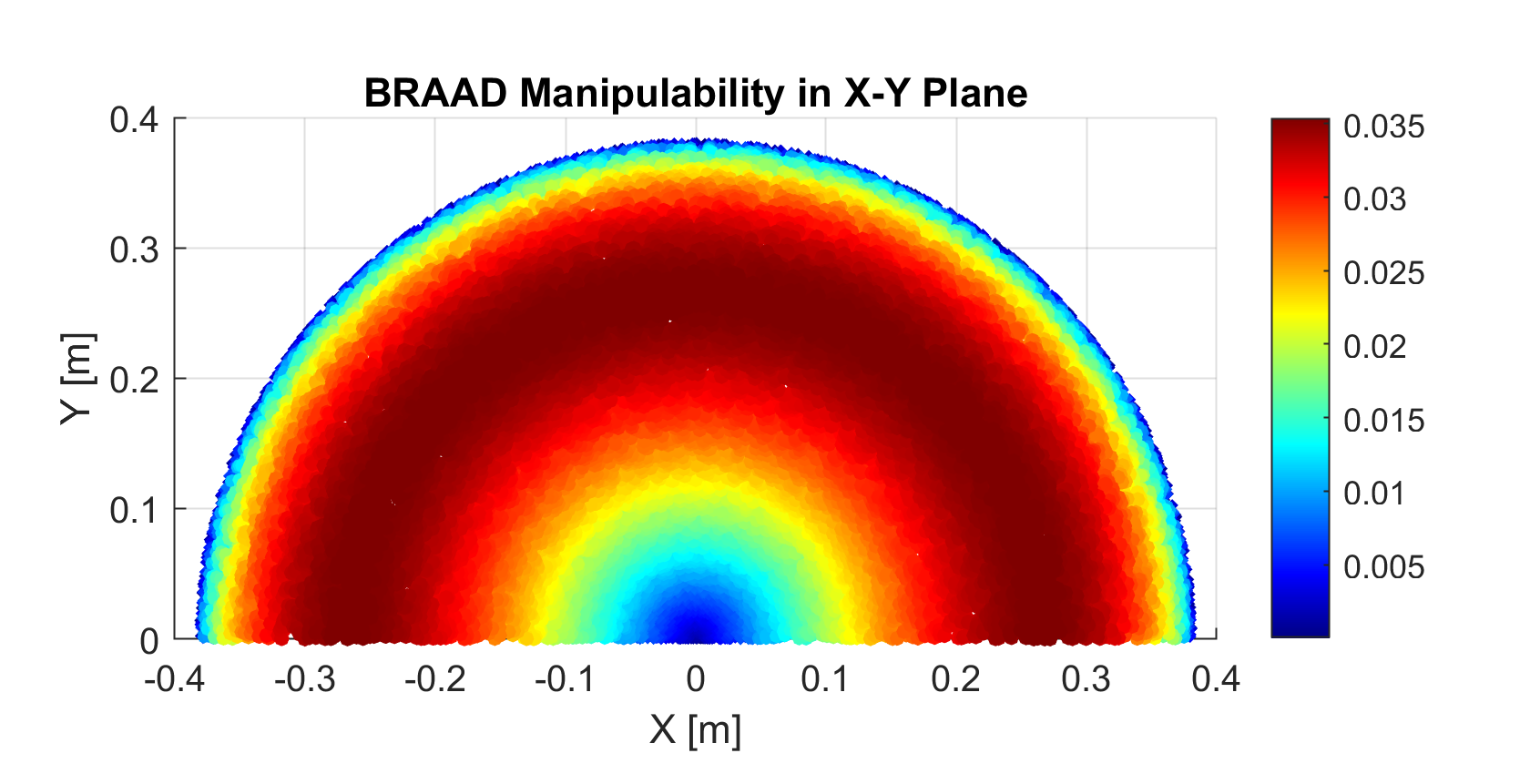
Trapping the ball inside the red region is the best case scenario since the end-effector will need to travel linearly along the ball’s path while maintaining a constant end-effector orientation. The robot would be capable of more effectively performing the required maneuvers to cushion the ball if the point of interception were inside a region of high manipulability.
While the analysis is useful for visualization, it is computationally expensive to compute manpulability of predicted future positions of the ball in real-time, which can significantly slow down the controller. This is undesirable when the system only has fractions of a second to select the best interception point and generate the trajectory to reach it as the ball approaches. Thus, instead of calculating the manipulability metric and evaluating all potential interception points, this process was simplified by designating a “circle of best manipulability”, lying in the center of the region of highest manipulability. This circle was determined to have a radius of 0.265 m from the base of the manipulator, and can be seen as red dotted circle in Figure 5.
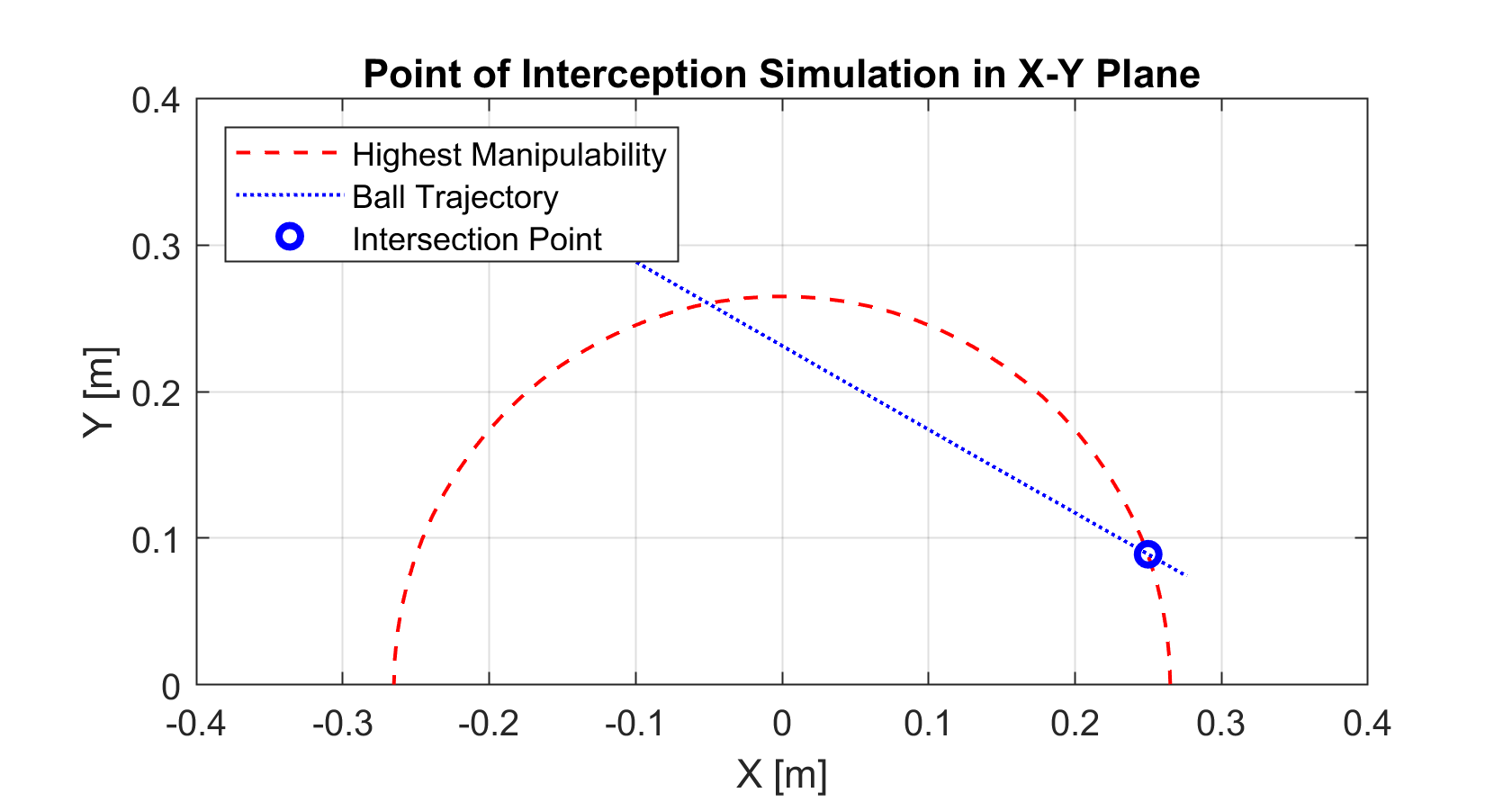

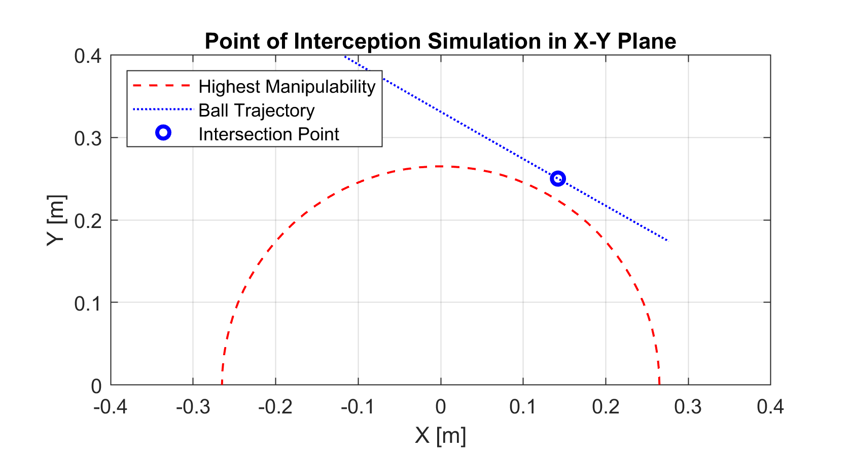
To generate the ball’s predicted trajectory, the vision system captures the most recent 5 frames and determines the ball’s X-Y position, direction, and speed in the global frame. From these data points, the system calculates a predicted ball trajectory which forms a straight line through the workspace, as seen in Figure 6. If this line intersects the circle of best manipulability, the system selects the intersection that is closest to the end-effector’s current position and generates joint trajectories (Figure 5). Otherwise, the system selects the point on the ball’s trajectory that is the shortest distance from the circle (Figure 7).
Position Controller
With the point of interception and predicted ball trajectory identified, BRAAD must now move the end-effector to intercept the ball. First, the system takes the desired end-effector position and uses inverse kinematics to generate a set of desired joint positions that will navigate the end-effector to the point of interception. These are then fed into each Dynamixel motor’s internal position controller as desired joint positions (Figure 8). The controller then generates a desired trapezoidal joint trajectory profile. Finally, the motor PWM output is calculated based on the feedforward and PID control terms. The PID control loop uses the encoder value as feedback to drive the error between the present and desired joint positions to zero. Each Dynamixel controller takes user-defined \(K_p\), \(K_i\), and \(K_d\) values. A total of nine gains need to be tuned for BRAAD’s position controller.
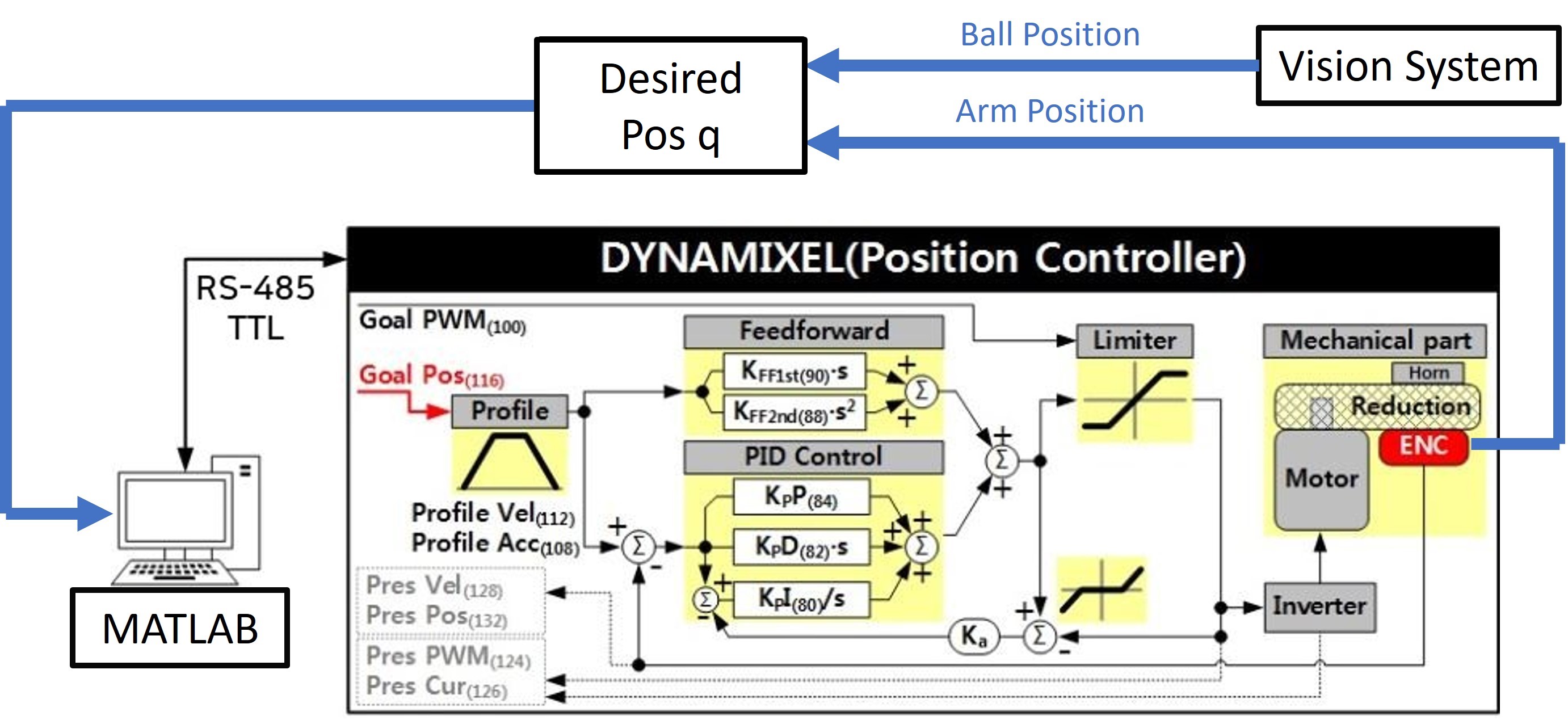
To improve the system’s robustness, a subroutine was implemented in MATLAB that uses the vision system to constantly update the desired position. By sensing the ball’s current location at certain timesteps, the system actively changes the predicted ball trajectory in real-time. The subroutine allows the system to adjust if the ball deviates from a straight path due to non-level ground conditions.
Velocity Controller
Once the point of interception is reached, the robot must then establish controlled contact with the ball. This requires the end-effector to be moving at the same velocity as the ball at the moment of contact to prevent it from bouncing off. Since the ball’s predicted trajectory is known, the end-effector can be commanded to move along that path until it reaches the edge of its workspace. However, since the arm is at rest, it is difficult to time the acceleration to match the ball’s velocity precisely.
To assist with contact timing, the vision system subroutine is used again. This time, the ball’s present location is compared to the end-effector’s current location, which is found using forward kinematics. When the ball is a certain distance away, the velocity controller is activated. This threshold distance is calculated using the magnitude of the ball’s velocity to grant the end-effector just enough distance to accelerate to the desired velocity. A user-defined time \(t_{accel}\) determines the overall time for acceleration.

The velocity controller (Figure 9) uses the inverse Jacobian to calculate the desired joint velocities:
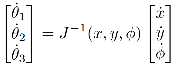
In this equation, \(\dot x\) and \(\dot y\) are equal to the ball’s last known X and Y velocity in global space, since this is the velocity that we want to match. \(\dot \phi\) is set to zero since the ball is traveling in a linear path and we do not want the end-effector’s orientation to change in global space.
The desired joint velocities are then sent to the Dynamixels internal velocity controllers. These generate trapezoidal velocity profiles with accelerations based on \(t_{accel}\) to ensure the end-effector has the desired velocity during contact. Once contact is established, a deceleration subroutine activates to reduce the velocity until the ball and end-effector reach zero velocity. Each Dynamixel controller takes user-defined \(K_p\) and \(K_i\) values, along with \(t_{accel}\) giving us a total of nine parameters to tune for BRAAD’s velocity control.
Results
Gain Tuning
Above is a demonstration of trapping a moving object. To get repeatable results, the ball was propelled using only gravity by placing it on a small 3D printed ramp. Doing so maintained a consistent position, direction, and speed between trials. For the first stage (position control), data was collected for BRAAD’s joint angles \(q_1\), \(q_2\), and \(q_3\), as well as desired reference angles \(q_{1des}\), \(q_{2des}\), and \(q_{3des}\). Additionally, the timestamp \(t\) after each control loop was recorded to keep track of the time between frames. The ball’s position in the global X-Y frame was also recorded as \(x_{ball}\) and \(y_{ball}\). For the second stage (velocity control), data was collected for BRAAD’s joint velocities \(\dot q_1\), \(\dot q_2\), and \(\dot q_3\), as well as desired reference velocities \(\dot q_{1des}\), \(\dot q_{2des}\), and \(\dot q_{3des}\).
After many iterations, the best gains were determined (tabluated below):

The joint positions and velocities with gained tunes are shown in Figures 10 and 11. Velocities were obtained using finite differentiation of the positions. The data shown for all joint velocity graphs has been subjected to smoothing using the last 10 values in the data due to the sensitivity of numerical differentiations to noise in the position data.
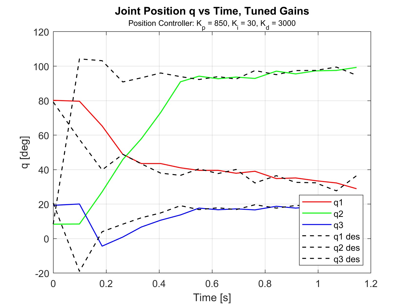
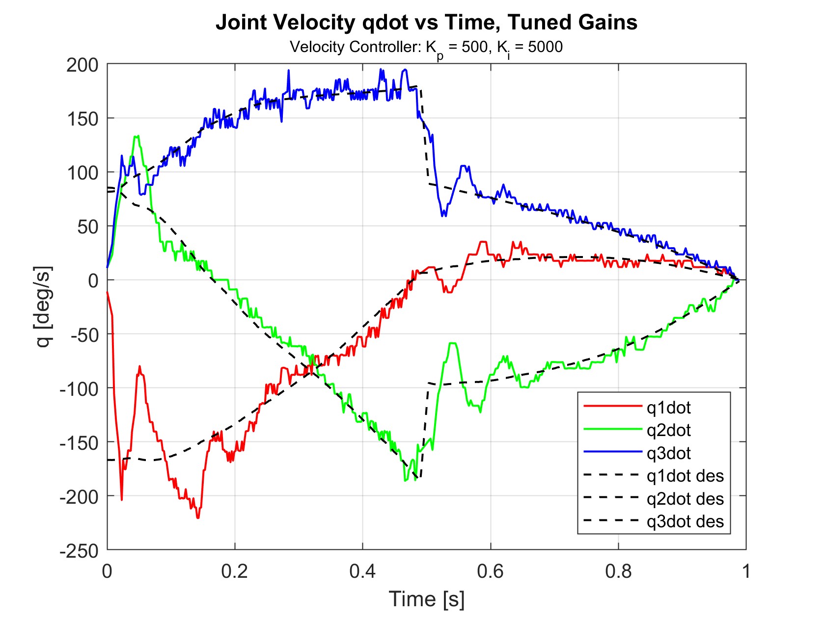
The selected position controller gains successfully achieved the goal of settling within 0.5 seconds. During trials, the robot could easily reach the interception point in time to receive the ball. The velocity controller was also able to closely follow the desired velocities, resulting in a well-timed contact with the ball and controlled deceleration.
Error Assessment
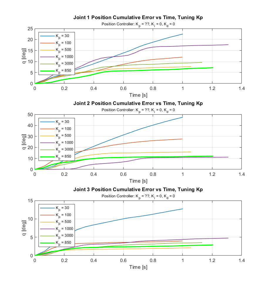
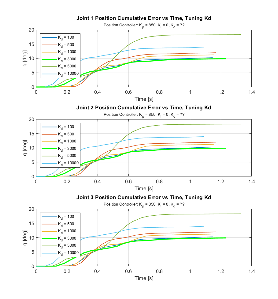
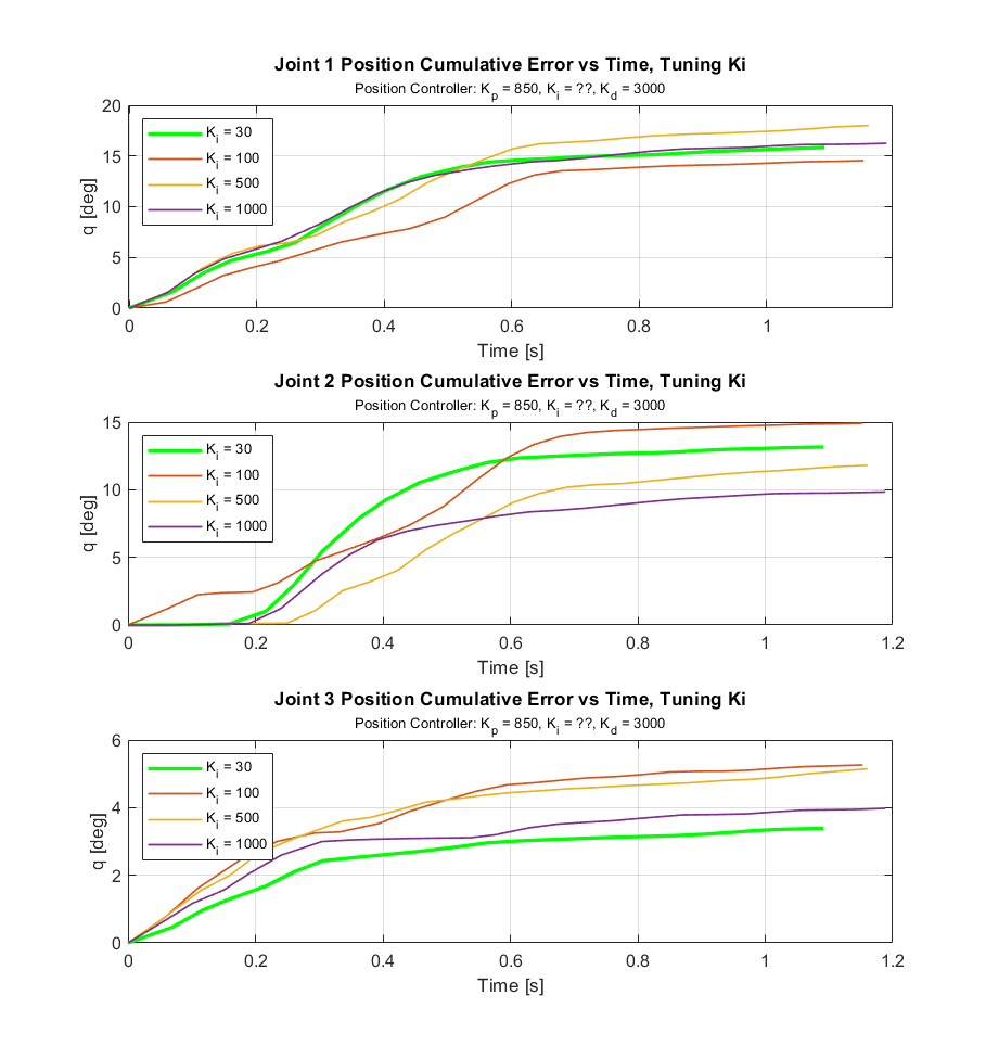
Because the desired positions and velocities for each set of gains were different, it was difficult to benchmark performance. To assist in selecting the best gain values and evaluating the performance of our system overall, the cumulative error for different gains was examined. When cumulative error becomes flat, it means that the system has reached steady state. The cumulative error is useful because it shows not only when the system has reached steady state, but also the total amount of deviation of the desired value. The chosen \(K_p\) gains are clearly the best set of gains because their accumulated error becomes flat in the shortest amount of time and has the smallest amount of accumulated total error.
Figures 12, 13, and 14 show the cumulative error data used to tune the \(K_p\), \(K_d\), and \(K_i\) gains for the position controller.
Figures 15 and 16 show the cumulative error data used to tune the \(K_p\) and \(K_i\) gains for the velocity controller.
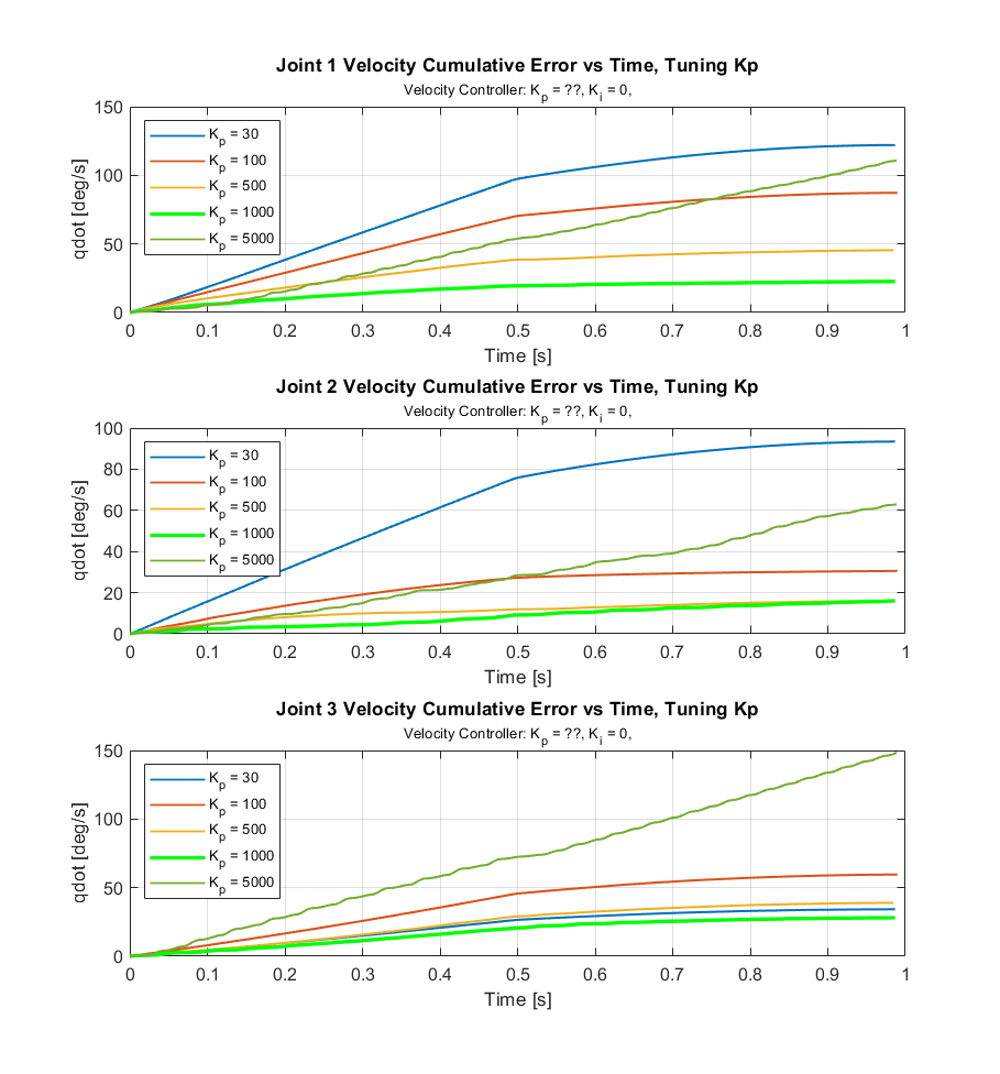
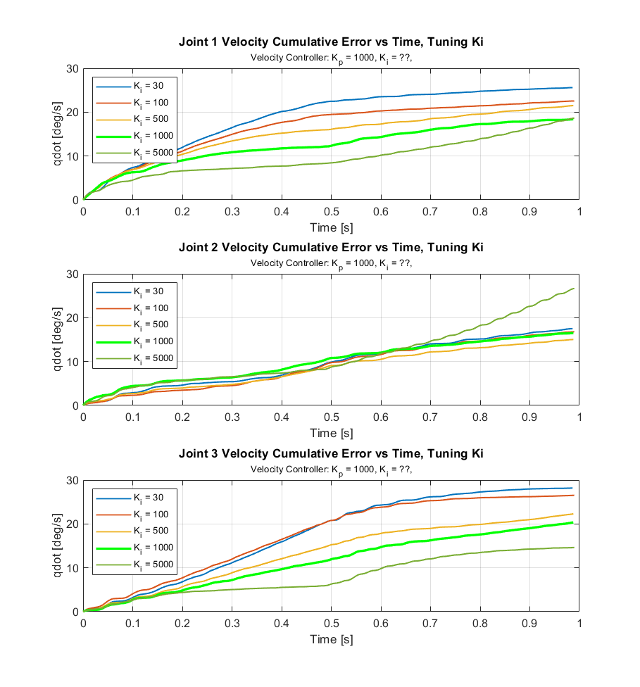
The gains that generated the least amount of error, minimal rising times, and shortest settling times were selected. In these error graphs, the selected gains are in bright green.
Discussion
Effects of Gain Tuning
For the position controller, \(K_p\), \(K_i\), and \(K_d\) were set to be the same for all joints while tuning. Similarly, for the velocity controller, \(K_p\) and \(K_i\) were the same for all joints. Though trial repeatability and consistency was maximized by rolling the ball down the ramp from the same height for every trial, there were small variations between trials due to human error. Figures 17 through 21 show the joint positions and velocities depending on the gains. The positions and velocities in bright green indicate the best gains found. The blacked dashed lines indicate the desired positions and velocities during the trial when using the best gains. Only the positions and velocities of joint 2 are shown because the effects of different gains were most exemplified for joint 2.
Position Controller
Figure 17 shows the results of tuning \(K_p\), with \(K_i\) and \(K_d\) set to zero. \(K_p\) values below 100 did not reach the interception point in time to receive the ball. The best value was explored between 500 and 1000, which slightly undershot and overshot the desired values in their respective trials. A \(K_p\) value of 850 was found to be best, reaching the desired position within 0.6 seconds.
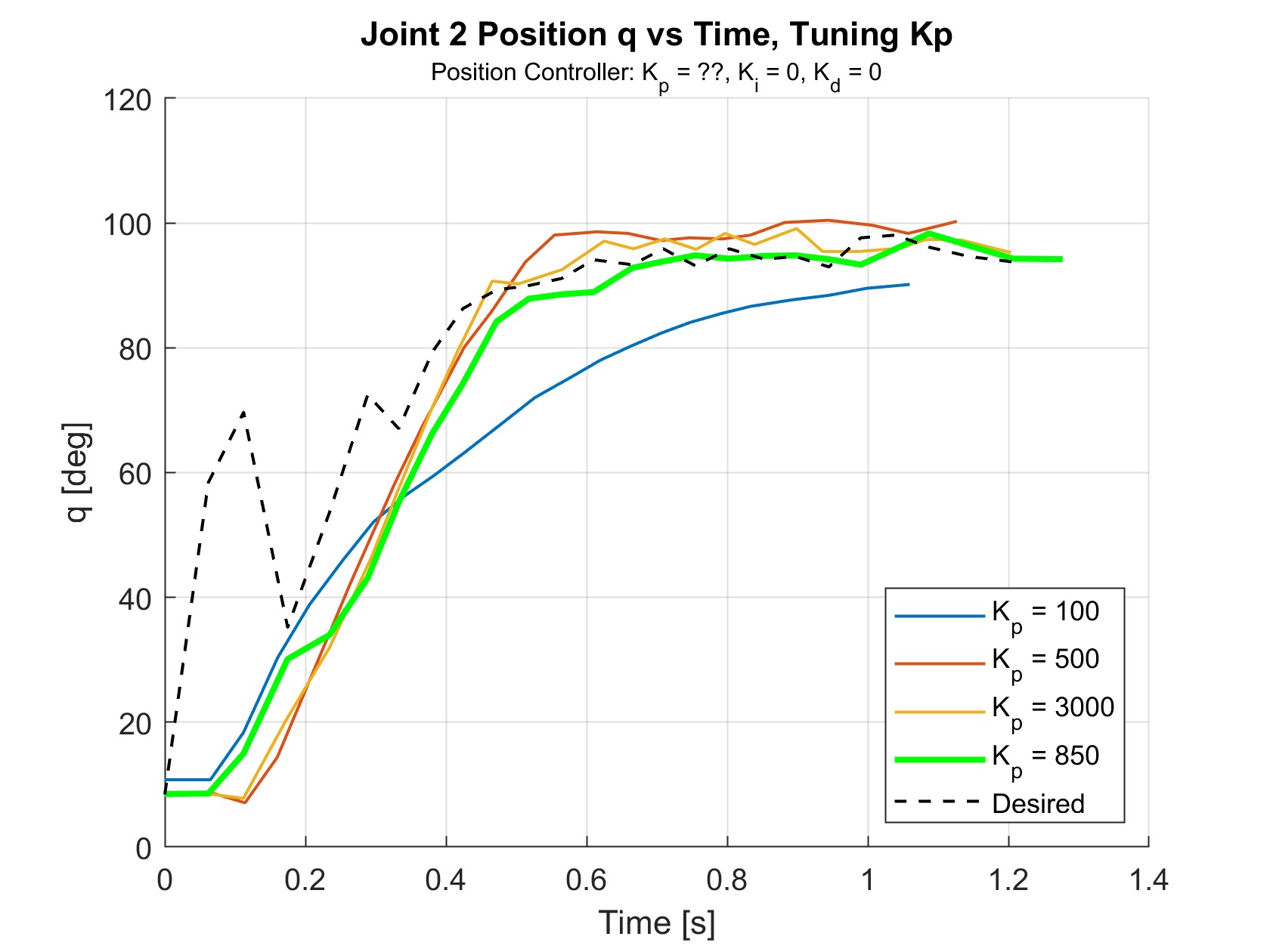
Figure 18 shows the results of tuning \(K_d\), with \(K_p\) = 850 and \(K_i\) = 0. Looking at t = 0 to 0.3 s, increasing \(K_d\) appears to improve the response time as the signal begins to rise sooner. \(K_d\) = 3000 was chosen to have the best performance across all three joints, even though \(K_d\) = 10000 had a quicker response time.
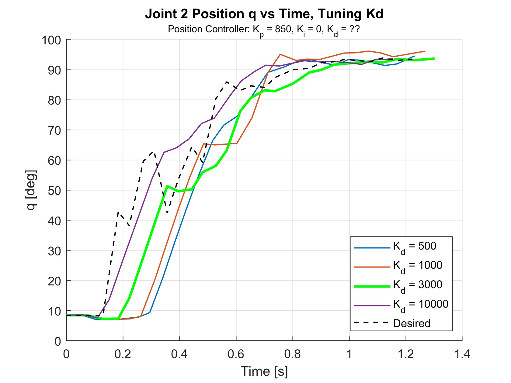
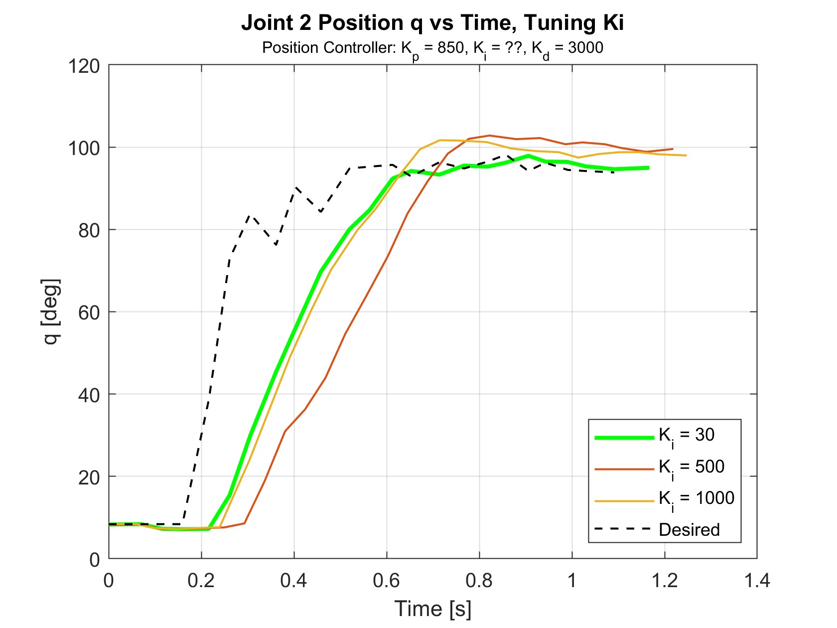
Figure 19 shows the results of tuning \(K_i\), with \(K_p\) = 850 and \(K_d\) = 3000. \(K_i\) eliminated many of the “bumps” in the movement, but did otherwise not have a large effect. \(K_i\) = 30 was chosen because the joint tended to overshoot when \(K_i\) was further increased.
While the effects of changing \(K_p\) matched the expectations of how P gains influence performance, the same cannot be said about the I and D gains. Increasing the I gain was expected to improve the steady state error and possibly cause more oscillations. Instead, the addition of the I gain to the controller removed oscillations. D gains are typically used to add damping to the system and reduce overshoot. Instead, the D gain succeeded in helping the system respond quicker and reduce the steady state error. These observations suggest that gains may have been switched during the implementation of setting the gains. The implementation showed no errors as the gains were assigned according to the documentation provided by the Dynamixel SDK. However, after further meticulous review, it was confirmed that the documentation is ambiguous about the gain addresses for the I and D gains. As seen below, the table suggests that the address of the D gain is 80, but the diagram shows the address of the D gain as 82. Additionally, the table says the address of the I gain is 82, but the diagram shows the address of the I gain as 80. Based on the responses when tuning these values, the diagram is in line with what is expected.
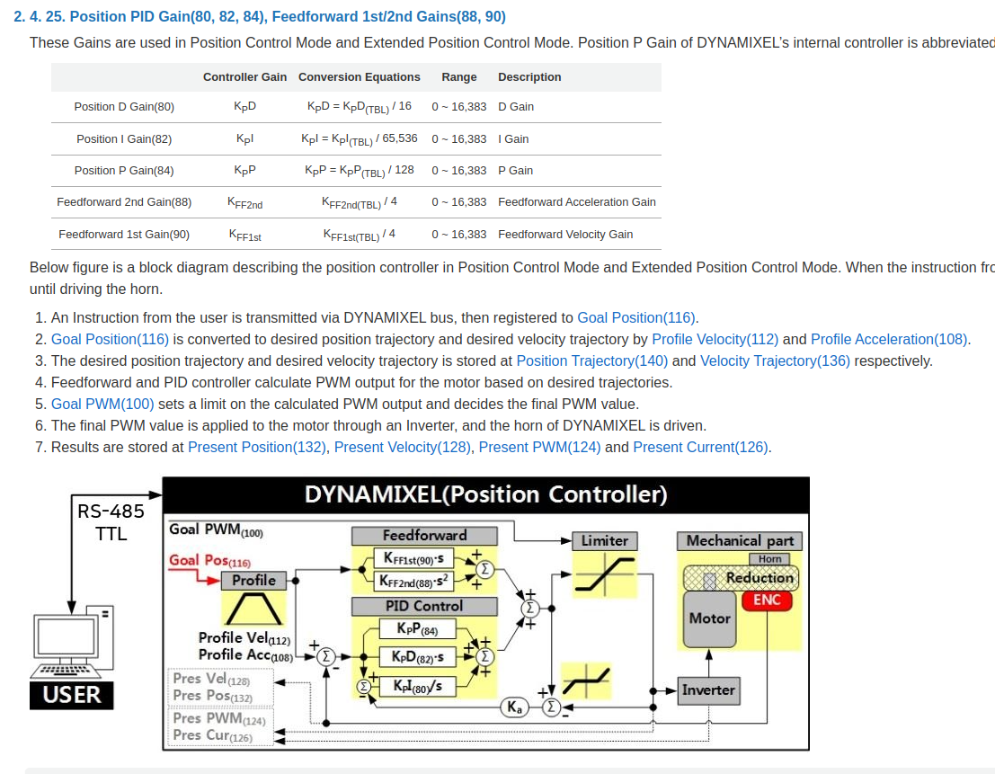
Link to documentation: https://emanual.robotis.com/docs/en/dxl/mx/mx-28-2/#position-d-gain
Velocity Controller
Figure 20 shows the results of tuning \(K_p\), with \(K_i\) = 0. For these trials, values lower than \(K_p\) = 500 did not produce velocities high enough to reach the desired velocities at all. \(K_p\) = 1000 did the best at matching the desired values while having minimal oscillations. For very high \(K_p\) values in the thousands, the oscillations became very large, which resulted in violet shaking and imprecise ball contact.
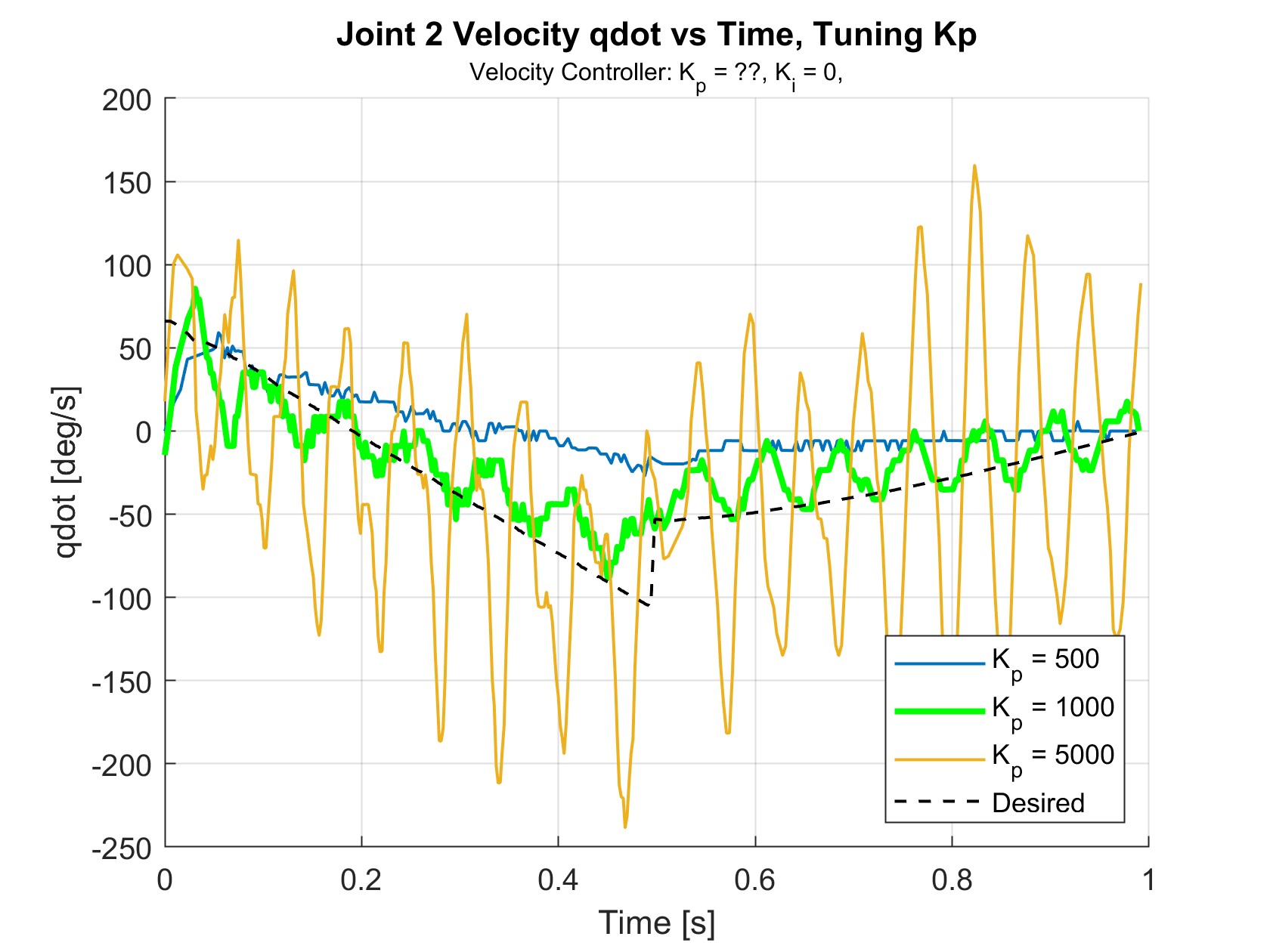
Figure 21 shows the results of tuning \(K_i\), with \(K_p\) = 1000. This resulted in significantly reduced the magnitude of the unwanted oscillations.
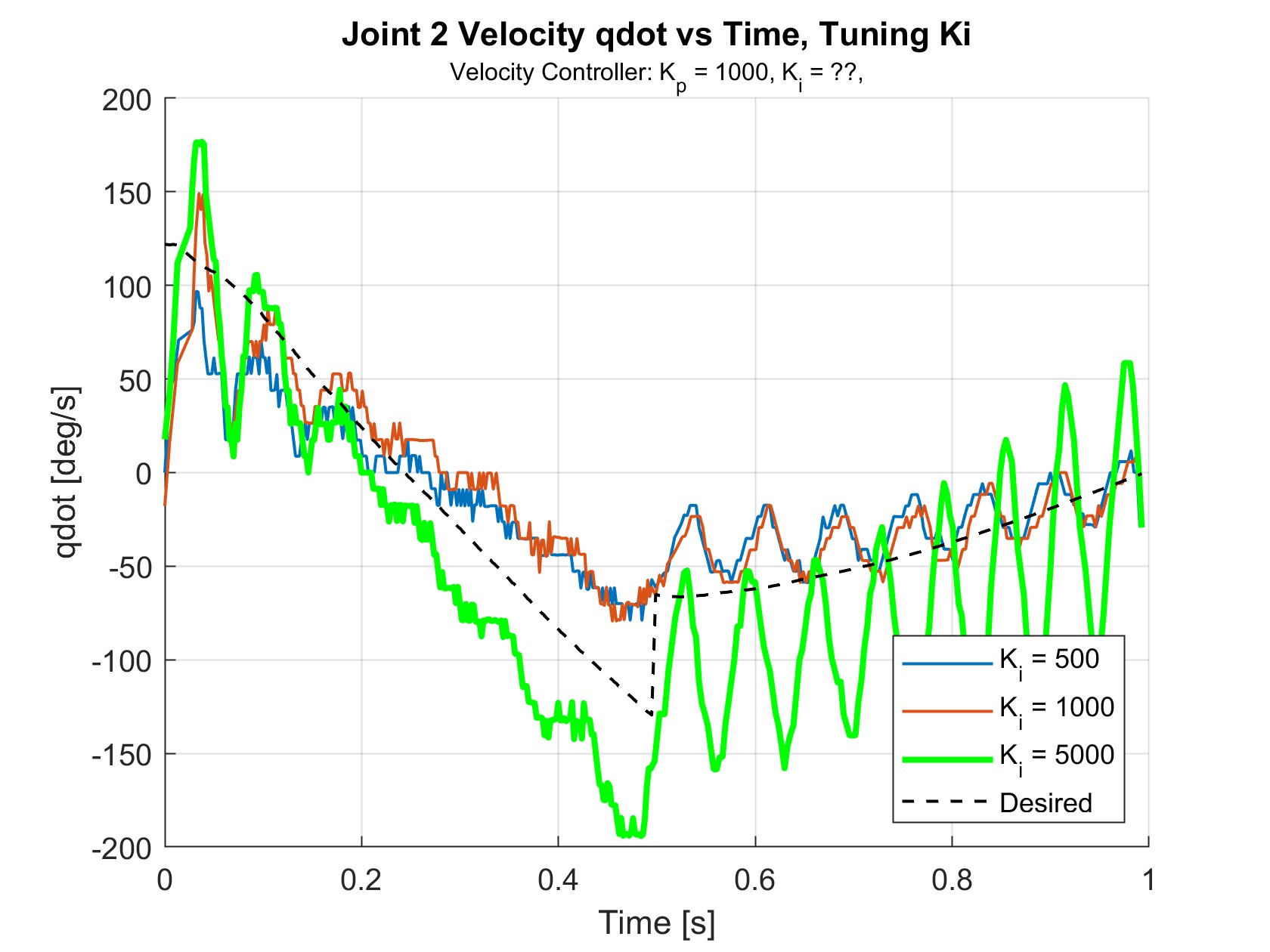
Because none of the iterations with \(K_p\) = 1000 looked promising, \(K_i\) was fixed and \(K_p\) was re-tuned. \(K_i\) = 5000 was selected because it looked to be the only \(K_i\) that drove the velocities closer to the desired velocities. With \(K_i\) = 5000, \(K_p\) = 500 looked to show the best velocity tracking performance as seen in Figure 16 (shown below again).

Controller Performance
Overall, the position controller performed excellently at tracking the ball in real-time and moving quickly to a desired position. After a short initial delay of 0.1-0.2 seconds from gathering frames, the arm would move to the interception point and typically settle within 0.5 seconds, which was found to be more than sufficient for the max ball velocity of 1 m/s. The velocity controller performed similarly well, closely following the calculated velocity path that would intercept the ball at its matched velocity.
While most attempts were successful, the system would sometimes intercept the ball at the wrong velocity, causing the ball to bounce off. This is because of inaccuracies with the vision system, which could not always accurately calculate velocity due to the frames not capturing at a regular speed. These hardware limitations could be exacerbated by changes in lighting or camera focus.
Due to the use of decentralized control, the controller did not perform well at ball speeds above 1 m/s, or when timing parameters such as \(t_{accel}\) were set to be too fast, causing significant dynamic coupling effects that were initially assumed negligible. This behavior could be seen on the position and velocity graphs as the first and second links fought each other to reach their desired positions. These torques could ultimately move the end-effector far enough off course to impact the ball in unintended ways, resulting in various phenomena, such as the ball being forced beneath the end-effector or being kicked away.
The controller was also limited by the sequential algorithmic structure. With the current ball’s testing speed, the impact was minimal, but for higher ball speeds, the algorithm did not have enough time to capture and process the frame data at 30fps. It would not respond quickly enough to reliably trap balls traveling through the workspace faster than 1 m/s.
Future Work
A primary theme for future work surrounds increasing speed and response time. Soccer passes and shots, even at youth level, average speeds around 23 m/s, which would be around 6.5 m/s when scaled.
One simple change to improve reaction time would be to increase the amount of time the vision system has to track the ball before it enters the workspace. This could be achieved by angling the camera horizontally, which would allow the ball to be detected from much further way.
Running the motor control and image processing in parallel instead of in sequence would also reduce the computational time. Additionally, using a different integrated development environment (IDE) would be more suitable than MATLAB for real-time application. Avenues for exploration might include the use of a separate microcontroller handling the interception or velocity planning for the motors. This would allow the primary computation unit (a laptop) focus on computer vision. Communication between the two would involve the sending of a packet containing the most recent ball locations. This communication might take place over Serial for an Arduino micro controller, or via I2C protocol for a customized controller and board.
Other optimization attempts could involve transitioning from MATLAB to a system supporting parallelism. In this scenario, the threads involving computer vision might be run on one core, while threads responsible for motor control and trajectory generation threads might be run on secondary and tertiary cores. Further testing would be required to determine the appropriate computational division and necessary data sharing.
Since this project operated mostly in the transient region, using a centralized controller might be preferred for a faster approaching ball speed. As the arm is required to move at faster speeds in order to intercept faster moving balls, using an inverse dynamics controller would be a logical next step to improving the arm’s dynamic performance.
Furthermore, soccer and other ball sports are played in 3D space. Future work can be built upon this 2D project by adding an additional degree of freedom in the direction out of BRAAD’s current motion plane (z-direction). Without additional of multiple cameras, the system could use the size of the blob relative to the true size of a soccer ball to approximate its position. Alternatively, supplementary cameras could be used to track in multiple reference frames. Another method is using IR light and retro-reflective markers to localize an object in 3D. These may enable a wider variety of trapping sequences and maneuvers in 3D. For example, the arm could intercept the ball in midair and press it into the ground to trap it.
Further applications to other ball sports and human robot interaction could be another field to explore with BRAAD in the future. The action of softly cushioning incoming the objects is ideal in the context of fragile biological organisms. The controller could also be applied in a reverse framework: consider the manipulator arm moving towards a target rather than the target moving towards the manipulator. This interception method could then be used to cushion the manipulator from the target, decelerating it similar to a landing action.