LIMMS
Latching Intelligent Modular Mobility System
Overview
Latching Intelligent Modular Mobile System (LIMMS) is a 6 degree of freedom symmetric serial robot where each end can detach and reattach to function as the base or the end-effector. LIMMS was designed as a robotic solution to package transportation by minimizing spatial footprint while maintaining task scalability. Check out the paper by the Robotics and Mechanisms Laboratory (RoMeLa) for more information and details on the feasibility of LIMMS and its potential as a transportation solution.
Inverted Pendulum Mode
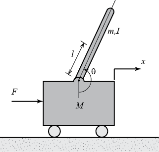
In order for LIMMS to operate as the package’s mobility system, LIMMS needs to be able to move individually to proper locations in the right orientation around the package. To achieve individual mobility for LIMMS, I modeled LIMMS as an inverted pendulum (Figure 1), which is already well established in literature and learning curriculums and even in commercial products such as Segways (Figure 2).

I imported the URDF of the LIMMS module into PyBullet to verify the inverted pendulum model as a mobility mode as seen in Figure 3.
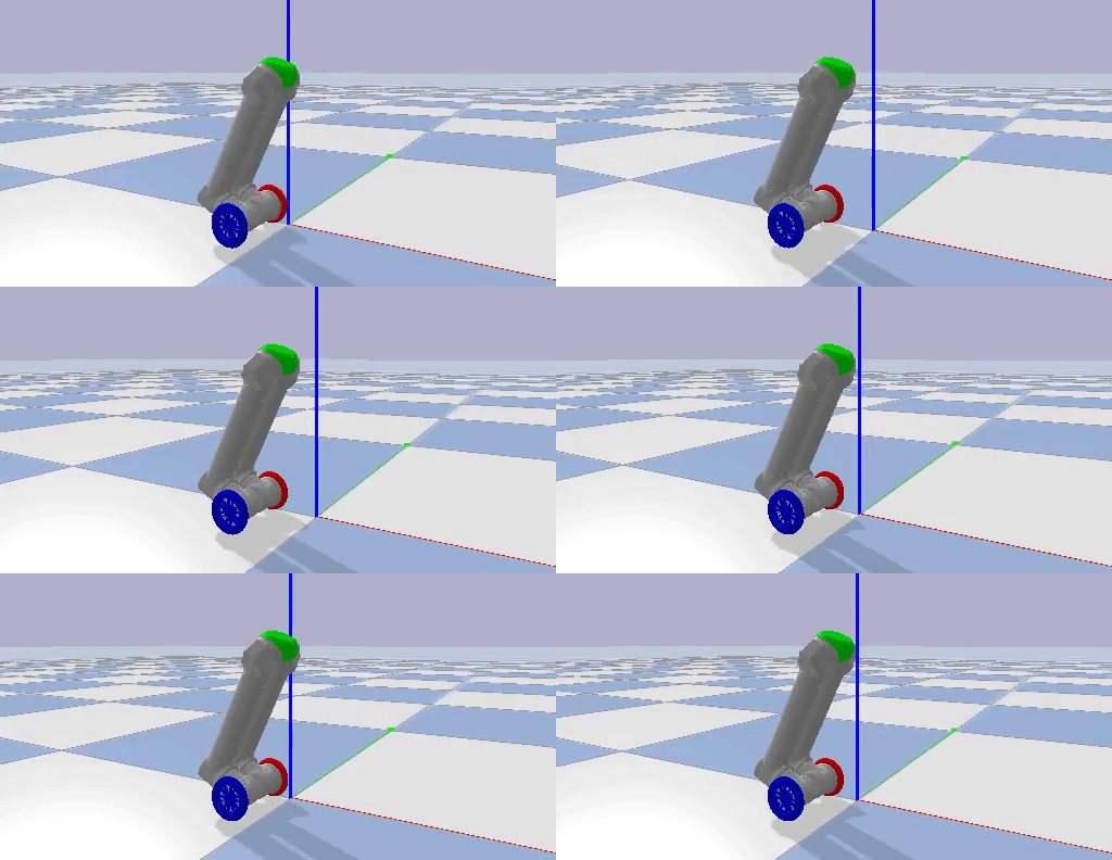
I implemented two PID controllers by actuating the wheel motors, holding all the other joint motors in place, and using the pitch of the center piece at the top of LIMMS as feedback to regulate the orientation of LIMMS. Through trial and error, I found the balancing pitch where LIMMS would mostly track a single position. One PID loop was used to regulate the orientation of LIMMS, while the other was used to track a certain desired position in the environment. Examples of LIMMS tracking a position, driving forwards, and turning are shown below.
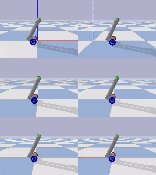

I also implemented the controller on hardware. I placed the inertial measurement unit (IMU) on the center of LIMMS and communicated with the IMU through WiFi. Unfortunately, the communication with the IMU was unstable and had high latency (Figure 4). The instability of the connection can be observed by the late actuation of the motors during changes in the pitch of LIMMS. The lack of latency can be observed in simulation by how the wheels can never reach the location below the center of mass of LIMMS in time, even with a high I gain in the balancing PID controller. I verified the effect of latency on balancing by running the simulation in both 90 Hz and 240 Hz (Figures 5 and 6). The simulation and hardware implemenations with low latency show similar behavior of how the wheels are increasingly late.

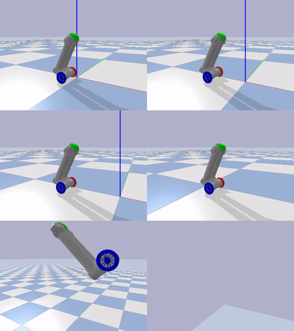
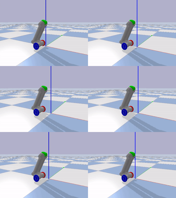
To address the issue of latency and connection instability, the IMU was switched to an IMU from MicroStrain and the connection was switched from WiFi to serial. After making the modifications, the hardware was able to successfully balance. Additionally, because the hardware was not run on battery, but instead was run through a wire, the dynamics are different from simulation, which means the dynamic equilibrium is different on hardware. Through trial and error, I found that the difference in the equilibrium angle was about 9 degrees. Below are videos of the balancing system.
Stable Orientation using Optimization for Tri-wheeled Mode
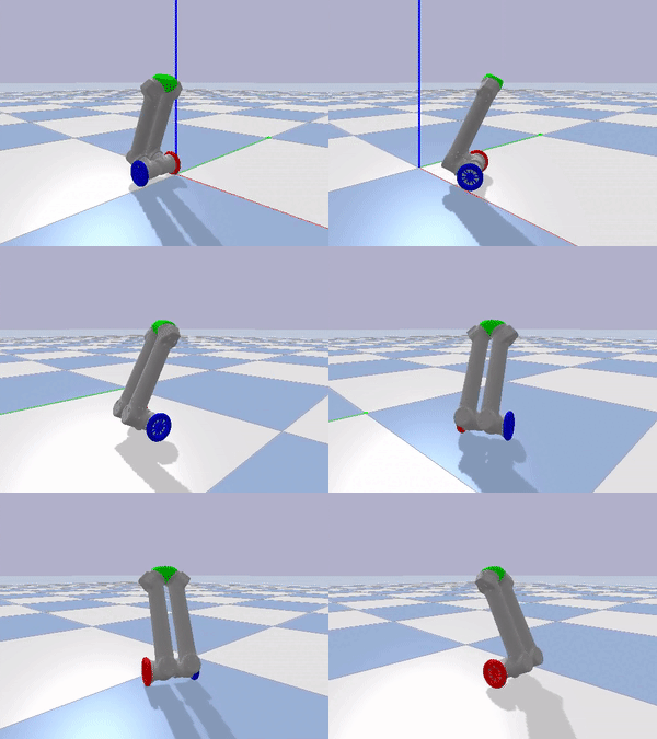
While the inverted pendulum method of mobility may be interesting, it is not necessarily feasible. The stability of the module may be influenced in the roll direction if the surface is not flat, which is not guaranteed in human environments. From an energy efficiency perspective, the module is required to continuously be operational and consume energy to stay balancing. At RoMeLa, we came up with a new mode called Tri-wheeled mode where two LIMMS modules are connected to each other and form a tricycle configuration. However, as seen in the video, the Tri-wheeled mode occupies far more space compared to the inverted pendulum mode.
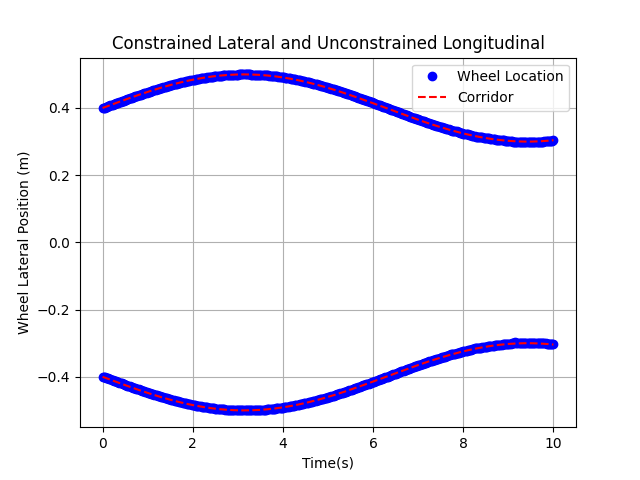
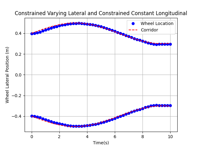
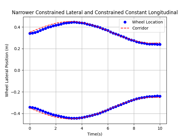
I used SciPy’s optimization library to find the optimal configuration of the Tri-wheeled mode. I constrained the lateral and longitudinal widths of the mode and maximized the area of the support polygon. Below are videos and figures that show the effet of different constraints. When the depth of the wheels are not constrained, it can be observed that the wheels stretch out as far as possible to maximize the support polygon area (Figure 7). The configuration seems to “bunch up” when both the width and depth are constrained (Figures 8 and 9).
References
2024
- Self-Aligning Rotational Latching Mechanisms: Optimal Geometry for Mechanical RobustnessJournal of Mechanisms and Robotics, 2024
2022
- Feasibility study of limms, a multi-agent modular robotic delivery system with various locomotion and manipulation modesIn 2022 19th International Conference on Ubiquitous Robots (UR), 2022
- Self-aligning rotational latching mechanismsIn International Design Engineering Technical Conferences and Computers and Information in Engineering Conference, 2022